Networks Horizon

share

Saturday 31 March 2012

Quality of Service (QoS)-Part2

QOS deploying Methods


==>CLI-Command Line Interface 
  •  Legacy Method
  •  Interface by Interface config
  •  Non Scalable as MQC
  •  Old method
  • Configuration overhead
==>MQC-Modular QoS CLI
  • Class Maps,Policy Maps and service map
  • Create groups of policies.

==>Auto QoS
  •  Just a command with few parameters
  •  Template based
  • Need to tune based on network specification.
==>QoS policy Manager (QPM)


Ciscoworks and QPM
  •  Gives graphical view of network
  •  Integrate into cisco works
  •  It can deploy QOS on whole network simultaneously and consistently.
QOS Mechanism


1.Classification
  •  (Class Maps)
2.Marking
  •  (Policy Maps)


3.Congestion Management
  •  Various Queuing methods
4.Congestion Avoidance
  •  FIFO and Tail Drop default
  •  Random Early Detection (RED)
  •  Explicit Congestion Notification (ECN)
  •  Weighted RED (WRED)
5.POLICING and SHAPING
  •  Policing drops (or remarks) excessive traffic
  •  Shaping delays excessive traffic
6.Link Efficiency Tools
  •  Link  Fragmentation and Interleaving (LFI) -Chip Chop big packets
  •  Compression


Tuesday 27 March 2012

Enterprise Campus Network
As already discussed, there are four Major functional Module in Enterprise Campus Network

1. Campus Infrastructure Module
  • Building Access 
  • Building Distribution 
  • Campus Backbone(Core)
2. Network Management Module
3. Server Farm Module
4. Edge Distribution Module

Key requirement for Enterprise Campus Network. 
Our Enterprise Campus Network must maintain certain level of each one of these.


Functionality: Network should fuction properly as per expectation.
Performance: Network should have a constant performance and stable throughput.
Scalability:We all want our network to grow.Network should have such scalability (Physically and logically)
Availability:Network should have redundant connection to make it available all the time.
Manageability:Network should be manageable instantly from a single point
Cost Effectiveness:Keeping the cost minimum.

Cisco's Network Designer's have developed a methodology a seven steps process when designing a enterprise campus network. It is based on years of experience from designers.

1. Determine application and data requirement
  • Need to identify which application will be running at user end
  • What would be the bandwidth requirements
2. Design the logical Network
  • Subnets, VLANs
3. Design the physical network
  • Determine where to place layer 2 and layer 3 devices
  • STP, transmission media (copper or fiber)
4. Select specific Cisco network devices at each location and create topology diagrams
  •  Select specific network devices, type of routers,type of modems/switches, FWs, IDS
5. Select an IP addressing strategy and numbering scheme
  • IPv4, IP v6, sub-netting, summarization,
6. Select a routing protocols 
  • Based on performance, scalability and availability
7. Design the Edge Distribution Module
  • How to we send and receive data from Enterprise Campus Module
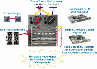
CISCO NSF with SSO

Cisco NSF (Non Stop Forwarding) with SSO (Stateful switch-over)
Cisco Nonstop Forwarding (NSF – also known as Graceful Restart) with Stateful Switchover (SSO) is a Cisco innovation for platforms with dual route processors (Cisco 7304, 7500, ASR1000, 4500, 6500, 7600, 10000, 12000 and CRS), allowing a NSF Capable router which has experienced a hardware or software failure of an active route processor, to maintain data link layer connections and continue forwarding packets during the switchover to the Standby route processor.

Nonstop Forwarding works with the Stateful Switchover (SSO) feature in Cisco IOS software. NSF works with SSO to minimize the amount of time a network is unavailable to its users following a switch-over. The main objective of Cisco NSF is to continue forwarding IP packets following a Route Processor (RP) switchover. It maintains and updates Layer 3 routing and forwarding information in the backup route processor. This ensures that the forwarding of IP packets and routing protocol information are continuous during the switchover and route convergence process. It eliminates router downtime, and increases network availability during scheduled maintenance of a route processor, or a route processor failure.

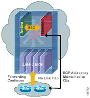
A Cisco router equipped with dual route processors can maintain Layer 2 data link connections and up-to-date “next-hop” information (FIB and Adjacency tables) to continue forwarding packets in the event of a route processor switchover until the routing protocols recover – In other words each protocol depends on CEF to continue forwarding packets during switchover while the routing protocols rebuild the Routing Information Base (RIB) tables. Once the routing protocols have converged, CEF updates the FIB table and removes stale route entries. CEF then updates the line cards with the new FIB information.

During switchover, system control and routing protocol execution is transferred from the active processor to the standby processor. The time required by the device to switch over from the active to the standby processor ranges from just a few seconds to approximately 30 seconds, depending on the platform.SSO is a prerequisite for NSF.

NSF can be used to improve network performance in a totally different way than traditional convergence, it Simply stops the reporting of neighbor failure, avoiding the need of re-convergence in the first place, while keep forwarding the packets until the neighbor resets its control plane. Using NSF you can virtually reduce network convergence to zero in case of control plane failures, but this implies the need for routers participating in this operation to be either NSF capable or aware, plus another critical implication which is that the failure must be recovered within the hold down timer limit of the protocol NSF/SSO benefit is not just nonstop forwarding, but also reducing route flaps, which is a significant factor in large scale networks, since route flapping results in all network routers converging after each route flaps, but with NSF/SSO no route flapping is reported – Since the NSF capable router(s) peers don’t report the NSF capable neighbor down to the rest of the network.

Objective
  1. Avoid TCP session to be interrupted
  2. User SSO in Layer 2 environment
  3. Use NSF with SSO at Layer 3.
  4. Reduce outages to 1-2 seconds avoiding single point of failure
  5. Supported by all cisco devices and routing protocols such as EIGRP, OSPF, BGP, ISIS etc
  6. Not supported on OSPF virtual links, HSRP does not work with NSF.
  7. From the CCIE SP Lab perspective it is only supported on the 7200 router on the lab equipment list.
Configuration Example: [For OSPF]

Router# show cef state <- Verifies that router is NSF capable
Router# configure terminal
Router(config)# router ospf 300
Router(config-router)# nsf
Router(config-router)# exit
Router# show running-config <- Verifies NSF for OSPF
!
router ospf 300
log-adjacency-changes
nsf                     <-------  nsf is used with OSPF
network 192.168.10.0 0.0.0.255 area 0
network 192.168.20.0 0.0.0.255 area 1
network 192.168.30.0 0.0.0.255 area 2

Cisco IOS Software Modularity

1. Operational consistency
2. Memory Protection
3. Fault containment
4. Process restart- ability (process can be start individually)
  • Command is Process restart <process> should be use with caution
5. Process Modularization (every process is different from other process)
6. Subsystem ISSUs (In service software upgrade)
  • A Selective system maintenance -during runtime
  • Versioning and patch management functionality
Benefits
  • Minimize unplanned downtime
  • Software up-gradation is simple
  • Modularity is maintained
Control Plane
  • EEM (Embedded Event Manager)-CPU utilization, SNMP, Syslog,counters
  • Routing Protocol
  • Multicasting protocol-PIM,IGMP
Data Plane
  • QOS
  • CEF
  • Access list
Management Plane
  • SNMP
  • CLI
  • Netflow


Saturday 24 March 2012

Enterprise Composite Network Model

It is highly available module design mechanism that make our network easier to scale,easier to comprehand and easier to troubleshoot. Now we are moving away from AVVID model to new and more scalable Model. Ealier we used to have a hierarchical model where we used to see it in layers like Core, Distribution, Access Layer.


Core layer: Its all about speed. Responsibility of this layer to switch traffic traffic from one point to another point in quickest amout of time.
Distribution layer: where packet manupulation and policy based connectivity is done (routers, multilayer switches running layer 3 services)
Access layer: Where customer plug in to the network(this layer contains customer router, switches, pc)


Enterprise Composite Network Model (ECN Model)-New Cisco Model

Above discussed three layers model did not completely go away. It has been absorbed and optimized in our new Enterprise Composite Network Model.

Three primary Modules/Areas:

  1. Enterprise Campus (LAN,Server farms, data centre)
  2. Enterprise Edge (Provides voice video and data services that going outside the enterprise, It allows to access internet and partner resources)
  3. Service provider Edge (ISPs, PSTN, FR/ATM/PPP)

Enterprise Campus

It has four sub-Modules.
1. Management Module (Authentication server,Controlnet server, monitoring server, IDS, syslog, system admin, out of band)
2. Building Module-Building Access, Building Distribution, Campus backbone(building core)

  • Campus backbone can have multilayer switches,routers.


3. Servers Module-Server Farms(Internal Email server, Corporate server, Web server,DNS servers,Print servers)
4. Edge Distribution Module-It connects campus backbone to Enterprise Edge

Enterprise Edge

Enterprise Edge (Provides voice video and data services that going outside the enterprise, I allows to access internet and partner resources). It uses edge distribution module to connect Enterprise Campus as already discussed.

We have four sub-modules here:

1. WAN Module (FR/ATM/PPP)

  • Connects Enterprise Campus to Service Provider Edge.

2. E-commerce Module 

  • Database servers, Application servers, Web servers,Security servers dealing with money and e-shopping.
  • We might have people coming through internet, so should have connectivity to Internet Module too.


3. Internet Connectivity Module 

  • Email servers,Security servers, Firewalls, public web servers

4. Remote Access/VPN Module

  • IPSec, DSL, ISDN, Dial an access.

Service provider Edge

It has several sub-modules.

  • Service provider Models(can have multiple ISPs for redundancy)
  • Public switch telephone Network Module
  • Frame-relay/ATM/PPP Module (Connects to  Enterprise Campus through Enterprise Edge) 


Enterprise Network Needs and AVVID Model

Networking Challenges: Performance, Scalability and Availability

Performance
Network performance decides how well network is going to perform. It is decided with the combination of a few facts called metrics:
  1. Responsiveness: How the user perceive the performance of the application in his view. Therefore, It is based on perception, doesn't matter how well your network graphs sees the network. So it has importance to users. If customer is not happy Responsiveness Metric is treated as BAD.
  2. Throughput: How many packets are going through per second. It is related to utilization. When throughput increases, utilization increases but after maximum limit throughput drops/ collapse. This is called congestive collapse for throughput. Therefore, throughput information is critical to Operational management.
  3. Utilization: Maximum utilization will eventually produce congestive collapse for throughput. So this needs to be checked that how much utilization we can have without having congestive collapse. It is important for Executive management.
Scalability
It is another area of concern for a Network designer. When designing a network following basic principals involves to imporve scalability of network:

Topology: Ensuring that changing the cabling, adding or removing network devices will not affect the existing network. So, we should have a plan in advance.
Addressing: Applicability of summarization and hirarical addressing wherever required and adaptability with new addressing schemes without affecting existing network
Routing Protocol:  An administrator has to decide and agree on a protocol which is suitable for the network. He must have concern on how scalable and suitable a routing protocol is for the network

Availability
A. Fault tolerance and redundancy
  •     Hardware redundancy ( Primary/Backup device)
  •     Link redundancy (Primary/Backup links)
B. Protocol resiliency (Routing protocol is able to handle the situation when routes are flapping or down)
C. Network Capacity Design: If we plan for the worse and never get there we can be successful as network a designers.

Two Models have been used to fulfil Enterprise Network Needs.
  1. Cisco's AVVID framework ( Architecture for Voice, Video and Integrated Data)
  2. Enterprise Composite Network Model-Cisco's Brand New design Model
Cisco AVVID framework
Today's networks transport an increasingly wide array of services such as voice and video, and application traffic including critical e-business and communication services. To assist network architects in the proper design of capable networks, Cisco created the Architecture for Voice, Video, and Integrated Data (AVVID).
  • It is not restricted to LAN/WAN and deals things enterprise-wise
  • It works as a standard and can be used with variety of product or various environment like Health care, Retail, Finance sector, Govt sector, Manufacturing or Education.
The AVVID architecture is based on an open, multiservice model and is composed of four interrelated, yet distinct layers as follows:
  1. Network Infrastructure Layer
  2. Services Control Layer
  3. Application Intelligence Layer
  4. Client Layer

Key components for AVVID framework
  • Common network infrastructure (routers, switches, voice GWs or whatever that makes a network.
  • Intelligent Network Services (Securing and controlling the environment like QoS, IPSEC, authentication, Network Management
  • Network Solution: Applications or final services like IP telephone, content Networking, Storage Networking
Building blocks of AVVID:
  • Network Clients and application servers (IP phones, PCs, wireless units, servers in Data Centre)
  • Network Platforms(routing/switching routers,switches,hubs, firewalls)
  • Intelligent Network services: like QoS(jitter,bandwidth, packet-loss), IPSEC,Autentication,Access list,Network Management (management tools), IP multi-casting (PIM,
Benefits of AVVID model:

Integration:

  • By using the Cisco AVVID architecture and applying the network intelligence imbedded within IP, companies can develop comprehensive tools to improve productivity.
  • Intelligence:

  • AVVID promotes the prioritization of traffic and delivers intelligent network services to maximize network efficiency and performance.
  • Innovation:

  • Cisco customers can adapt quickly to a changing business environment.
  • Inter-portability: Standards-based APIs enable integration with third-party developers.


    In next chapter we will discuss Cisco's Enterprise Composite Network Model

    Wednesday 7 March 2012

    Q1. The use of a loopback interface to define neighbors is common with iBGP, but is not common with eBGP. Normally, you use the loopback interface to make sure that the IP address of the neighbor stays up and is independent of hardware that functions properly. In the case of eBGP, peer routers frequently have direct connection, and loopback does not apply.
    is this true that we don't use loopback for eBGP.


    Ans: It is not so that we never use loopback address on eBGP neighborship . Sometimes, there might be scenario where you have two or more redundant path between two eBGP peers.
    link:
                         s0...................................s0 
    loopback-----R1                                        R2-------loopback
                         s1...................................s1
    To understand this first we need to understand why we need loopback addresses for IBGP connectivity.

    Similarly in eBGP there may be the case if one of the two available paths is un-available,  BGP neighborship will remain intact through loopback addresses because IP connectivity will remain there through alternate path.

    By the rule, eBGP neighborship should be directly connected but there may be another scenario where we should always use loopback address to create eBGP neighborship to utilize all the parralel available links( incase we have two or more direct links).
      
    neighbor ebgp-multihop, neighbor ttl-security hops commands are used where neighbors are not directly connected (neighbors are multiple hops away)
    neighbor disabled-connected command should be used where eBGP neighborship is formed via loopback address.
      
    like iBGP neighborship here also update-source <loopback int> should be changed alogwith. Also needs to remember that loopback interfaces are not physical interfaces and always remains up unless whole router is down.

    Alternatively dynamic static routing can also be used instead of using BGP for the purpose . Irrespective of BGP power, we should prefer static routing over eBGP which is easiler to configure and provides less CPU overhead.
      
    ISP environment
    While the external BGP (EBGP) sessions are usually established between directly-connected routers, IBGP sessions are expected to be configured across the network.

    Best iBGP Practices: Therefore, the current best practice is to configure IBGP sessions between the loopback interfaces of the BGP neighbors, ensuring that the TCP session between them (and the BGP adjacency using the TCP session) will not be disrupted after a physical link failure as long as there is an alternate path toward the adjacent router.
    Best eBGP Practices: Establish EBGP session on physical link and not via loopback interfaces unless nee there are more links between two EBGP