
Networking Layered Approach- OSI and TCP/IP
OSI Reference Model
OSI model was developed many years ago to break up the complex process of sending data from one computer to another computer in 7 steps or layers. This model identifies the steps and function that must be completed at each other when computers communicate over a network. These 7 layers are set of building block set on top of each other. The main drawback of OSI model is that it only provides guidelines on how computers communicate over a network but does not at all provide detailed procedures actually how this communication make to happen. These procedures of communication are called Protocols and defines how actual communication occurs.
So, a protocol is formal set of written rules or procedures that computers must understand, accept and use to be able to communicate over a network. Different protocols use difference layers of reference model. It is just like that two people need to speak same language to communicate, two computer uses the same protocol at the same layer for the data to be communicated. More than just a common language/method, protocols are rules of etiquette used in that language/method. Apart from all this, OSI layered Model also describes how data to be transfer from one layer to the next.
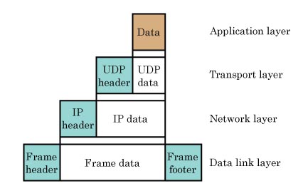
On the sending computer data flows down the model in the stack( from layer 7 towards layer 1). At each layer in the stack there are specific protocols and headers,trailers and footers which contain information such as addressing and error control information. When lower layer receives information from upper layer, it considers entire packet as data and adds its own header and if needed footer/trailer information to the data.

The processing of adding header/trailer information layer by layer down the stack is called encapsulation.
In the receiving computer, data flows up the stack (From layer 1 to Layer 7). At each layer, addressing and protocol information is examined and removed layer by layer until computer gets to the actual data in desired format. This process is called de-encapsulation.
In short, OSI reference model is theriotical in nature and does not define actual protocol.
TCP/IP

Top 3 layers of OSI model make up single Application layer of TCP/IP. Transport layer is unchanged and Network layer is now called Internet layer in TCP/IP. Network Access of TCP/IP covers two layers of OSI (Data link layer and Physical Layer). When we send an email, the email program on our computer like outlook first interact with the application layer. Behind the scene the email program sends message or data to your internet email server for delivery. Email application uses the SMTP (application layer protocol) for this communication.
Application layer protocol specifies details such as how data should be encoded,compressed or encrypted and how session should be managed. Application layer protocols examples : HTTP, SMTP, FTP, DNS.
Our data at this point is like a letter written in a language that recipient can understand. Application layer send the data down the stack to the Transport layer.
Transport layer specifies which application layer protocol to be used once data will arrive at receiving computer. Each application layer protocol is assigned a unique numerical identifier is called a port(software port). Port is used to identify application layer protocol. So incoming data on receiving computer can find
the correct program in the computer. For example HTTP uses port 80, DNS uses port 53 and SMTP uses port 25.
This port number is just like a recipient name on an envolope. Just like there might be multiple people living at the same address, there might be multiple programs running on a single computer. So transport layer adds its header and destination port number with the data, so once the data arrives at the destination computer, transport layer can identify the data and determine the application layer protocol where data to be sent to.
Transport layer also add the source port number in the header which is similar to the self(sender) address on the envelope (used for return receipt). Source port number is typically a random number which uniquely identifies the connection on sending side. It is nothing to do with application layer protocols. This port allows multiple session to be opened with sending computer without mixing the data among multiple requester.
Transport layer has another function. For example in real world, you can post letter in two ways:
- Simply post the letter and assume that letter is delivered to the recipient .
- Post the letter and request for a return receipt to know if letter is arrived to the correct recipient .
Transport layer offers similar choice of reliability with its Transport layer protocols TCP and UDP.
TCP and UDP (transport layer protocol in TCP/IP protocol suite)

TCP on the other hand is more robust protocol providing delivery notification, error checking and recovery procedures.Sending computer gets a delivery notification for each of its segments. It is equalant of getting a return receipt on a registered mail. HTTP, SMTP and FTP uses TCP. TCP accept the data from application layer protocol and cuts the data into smaller pieces called segments to ensure steady flow of data. Length of data field in Segments can be variable in size.
Segmentation is like taking our letter and sending each page of that letter on seperate numbered envelope. So that receipant can place them in order after receiving all. Likewise TCP assigns a sequence number to each segment so that they can be reordered in the destination transport layer.Moreover, destination side uses sequence numbers for sending back notification to sender machine. If sending machine do not receive specific acknowledgement in the reasonable amount of time, it sends the particular segment again with the same sequence number.Gateways and Cable tester work on this layer.
Once this process is complete, transport layer sends the data down to the network layer.
Network layer takes the segmented data and adds a layer 3 header. Now it becomes a packet. Network layer header contains source and destination IP address. These addresses also called layer 3 addresses or logical addresses. Please note that there is no need to inspect transport header or original data during the layer 3 encapsulation process. Network Layer add a protocol number field(number identifying the upper layer transport protocol) to know the nature of the original data. Please note that each transport layer protocol is assigned with a unique number(IP protocol number). For example UDP is IP protocol number 17 and TCP is IP protocol number 6.When we are sending an email. It uses protocol number 6 because SMTP uses TCP. At the destination router, Network layer protocol process and forward the data back to transport layer based on this application layer information(IP protocol number).
Layer 2 receives the packet and like its upper layers, it add its own header to the data and creates a frame. This layer uses another address which is commonly refered to layer 2 address or physical address or MAC address. Layer 2 header typically also includes an indication as to which layer 3 protocol is in the data portion of the frame. This way layer 2 come to know about layer 3 protocol without looking into original data and without striping the layer 3 information. Layer 2 also perform its data integrity checks so that damaged frame can be discarded as early as possible in the transmission process. This is performed by adding a check sum field in the trailer of the frame. Sending computer runs the computation and insert the check sum in the frames trailer. The network device receiving the frame runs the same calculation. If the computation results match, the frame is treated legal and accepted otherwise an error notification is sent to upper layer protocol (TCP/UDP) whether to do data recovery or not.
Finally layer 2 converts the data into the format that physical layer can understand(in binary 0s and 1s) before sending it to layer
Physical layer takes the binary information from layer 2 and converts the bit into electrical signals and send them across the physical medium which can be telephone wire, optical fiber or a wireless environment. Physical layer defines characteristics such as cabling specification, physical data rate, maximum transmission distances and connectors/ports.Physical layer also checks the number of bits transmitted per second and two ways or one way transmission. Physical layer also dealing with the optical, mechanical and electrical features. ISDN, IEEE 802 and IEEE 802.2.
No comments:
Post a Comment